25+ entity relationship diagram in software engineering
This exhibition of similar patterns at increasingly smaller scales is called self. On the ARPANET the starting point for host-to-host communication in 1969 was the 1822 protocol which defined the.
How To Draw A Comprehensive Entity Relationship Er Diagram Quora
Cloud computing is the on-demand availability of computer system resources especially data storage cloud storage and computing power without direct active management by the user.
. Entity-relationship modeling or ER Diagram symbols are part of a conceptual approach to design that models objects as abstract data types and the relations between these objects as predicates. Creating the entity-relationship ER model by visually representing the structure of some database mainly the business one which data equates to its entities or objects that are connected by relationships showing requirements and dependencies you need proper software to provide. The Unified Modeling Language UML is a general-purpose developmental modeling language in the field of software engineering that is intended to provide a standard way to visualize the design of a system.
The database diagram editor is drag-and-drop so you can object elements easily. It instead has a partial discriminator key. Mostly you will need to build codes and scripts for UML class diagrams or entity-relationship diagrams.
Systems engineering is an interdisciplinary field of engineering and engineering management that focuses on how to design integrate and manage complex systems over their life cyclesAt its core systems engineering utilizes systems thinking principles to organize this body of knowledge. Each block contains a cryptographic hash of the previous block a timestamp and transaction data generally represented as a Merkle tree where data nodes are represented by leafs. This lets us find the most appropriate writer for any type of assignment.
ER Diagram stands for Entity Relationship Diagram also known as ERD is a diagram that displays the relationship of entity sets stored in a database. The creation of UML was originally motivated by the desire to standardize the disparate notational systems and approaches to software design. One of the first uses of the term protocol in a data-commutation context occurs in a memorandum entitled A Protocol for Use in the NPL Data Communications Network written by Roger Scantlebury and Keith Bartlett in April 1967.
In mathematics a fractal is a geometric shape containing detailed structure at arbitrarily small scales usually having a fractal dimension strictly exceeding the topological dimensionMany fractals appear similar at various scales as illustrated in successive magnifications of the Mandelbrot set. We will guide you on how to place your essay help proofreading and editing your draft fixing the grammar spelling or formatting of your paper easily and cheaply. What is ER Diagram.
However you can also generate code from a UML state machine diagram or any other diagram type with custom-defined. Large clouds often have functions distributed over multiple locations each location being a data centerCloud computing relies on sharing of resources to achieve coherence and typically. In other words ER diagrams help to explain the logical structure of databases.
Unlike a strong entity a weak entity does not have any primary key. An entity-relationship model ERM sometimes referred to as an entity-relationship diagram ERD could be used to represent an abstract conceptual data model or semantic data model or physical data model used in software engineering to represent structured data. Reliability is closely related to availability which is typically described as the ability of a component or system to function at.
A simulation is the imitation of the operation of a real-world process or system over time. This information is usually described in project documentation created at the beginning of the development processThe primary constraints are scope time and budget. ER diagrams are created based on three basic concepts.
Entity relationship diagrams in software engineering. Our global writing staff includes experienced ENL ESL academic writers in a variety of disciplines. The Zachman Framework is an enterprise ontology and is a fundamental structure for enterprise architecture which provides a formal and structured way of viewing and defining an enterprise.
A blockchain is a type of Digital Ledger Technology DLT that consists of growing list of records called blocks that are securely linked together using cryptography. In contrast to typical federated identifiers DIDs have been designed so that they may be decoupled from centralized registries. 1 DbSchema DbSchema is a visual database designer manager for any SQL NoSQL or Cloud database.
What How When Who Where. It is often used as the basis for data flow diagrams or DFDs as they are commonly known. The tool enables you to visually design interact with the database schema design the schema in a team and deploy it on multiple databases generate HTML5 diagram documentation visually explore the data and build queries and so much more.
Generates reports as PDF Word or HTML. Project management is the process of leading the work of a team to achieve all project goals within the given constraints. The ontology is a two dimensional classification schema that reflects the intersection between two historical classifications.
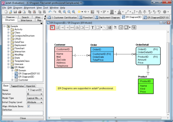
In software engineering an ER model is commonly formed to represent things a business needs to remember in order to perform business processesConsequently the ER model becomes an abstract data model that defines a data or information structure which can be implemented in a database typically a relational database. Automatic diagram generation for existing databases. The ER Diagram show the relationship between entities tables and the primary key-foreign key relationships between the tables relationships.
Decentralized identifiers DIDs are a new type of identifier that enables verifiable decentralized digital identity. All-in-one software - a suite of design analysis and management tools to drive your IT projects forward. Transform UML to code.
Entityrelationship modeling was developed for. Reliability engineering is a sub-discipline of systems engineering that emphasizes the ability of equipment to function without failure. A weak entity is represented by a double rectangle.
An entity is a thing person or. Reliability describes the ability of a system or component to function under stated conditions for a specified period of time. The relation between one strong and one weak entity is represented by a double diamond.
A DID refers to any subject eg a person organization thing data model abstract entity etc as determined by the controller of the DID. Entity relationship diagrams are used in software engineering during the planning stages of the software project. Software engineering concerns methods and techniques to develop large softwaresystemsTheengineering metaphoris usedtoemphasizea systematic approach to develop systems that satisfy organizational requirements and.
They help to identify different system elements and their relationships with each other. The individual outcome of such efforts an engineered system can be defined as a. Simulations require the use of models.
The model represents the key characteristics or behaviors of the selected system or process whereas the simulation represents the evolution of the model over timeOften computers are used to execute the simulation. There are several notations used for ERMs. Get 247 customer support help when you place a homework help service order with us.
The secondary challenge is to optimize the allocation of necessary inputs and apply. Entity Relationship Diagram 25 See All Data Field Entity Relationship Diagram. A weak entity is dependent on a strong entity to ensure its existence.
Entity Relationship Diagram Examples Crows Foot and Chens notation examples. Our code generator allows you to convert your diagrams to source code in various programming languages. Entities attributes and relationships.
CX UX 13. The tool uses entity-relationship diagrams to display the relationships between database entities. The first are primitive interrogatives.
What Are The Best Free Online Tools To Draw An Erd Entity Relationship Diagram Quora
How To Make An Entity Relationship Diagram Erd Of A Restaurant Quora
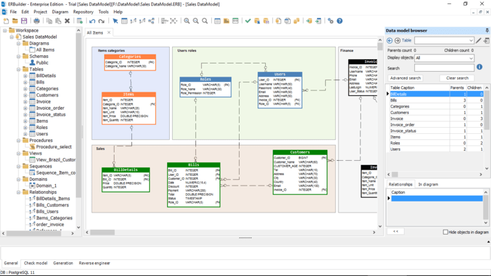
Erbuilder Data Modeler
How To Make An Entity Relationship Diagram Erd Of A Restaurant Quora

What Is The Entity Relationship Model Diagram Examples Video Lesson Transcript Study Com

What Is The Entity Relationship Model Diagram Examples Video Lesson Transcript Study Com

Mindfusion Diagramming For Winforms Professional

Data Flow Diagram Template Mural
What Are The Best Free Online Tools To Draw An Erd Entity Relationship Diagram Quora

What Is The Entity Relationship Model Diagram Examples Video Lesson Transcript Study Com
What Are The Best Free Online Tools To Draw An Erd Entity Relationship Diagram Quora

What Is The Entity Relationship Model Diagram Examples Video Lesson Transcript Study Com
What Are The Best Free Online Tools To Draw An Erd Entity Relationship Diagram Quora
Er Diagram Entity Relationship Diagram

Data Flow Diagram Template Mural
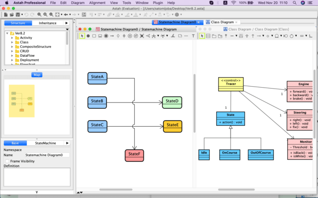
Astah Professional Screenshots

What Is The Entity Relationship Model Diagram Examples Video Lesson Transcript Study Com